System Design Document
Automatic Plant Watering Machine
System Design
Introduction:
The Automatic Plant Watering Machine (APWM) is a machine which monitors the moisture of the soil of four potted plants, determines if the soil is too dry and adds an appropriate amount of water to the soil to maintain healthy plants. The APWM can also apply a measured amount of water on a time schedule or accept commands over the internet to water the plants with a measured amount of water on command.
User Interface:
A user interface is needed to issue commands to the APWM, set up a watering schedule and to receive status messages. Two user interface implementations were considered: 1) use HTML and connect to the APWM using a browser or 2) use a Twitter account and communicate with the APWM via tweets. An interface implemented in HTML would provide a graphic user interface and would be intuitive but would involve more development time and would be more complicated. An interface implemented using twitter would be more difficult for a user because all commands and status messages would be text oriented. However, this method would be much easier to implement. Since there is a severe time constraint for implementation, it was decided to use Twitter for a user interface.
Command tweets sent to the APWM will have a specific format. If there is a syntax error in the command, the APWM will tweet back that there is an error in the command line.
This is a list of the commands that will be implemented as a minimum:
“SR” - status request. The APWM will respond with a tweet indicating the last time each of the four plants was watered and with how much water in milliliters, the current watering schedule if any and the amount of water remaining in the reservoir.
“RS” - reset the watering schedule and set the amount of water in the reservoir to full.
“SC P MM/DD/YY HH:MM QQQ X” Schedule a watering time. “P” designates which plant is to be watered with valid values of 1 through 4, “MM/DD/YY” designates month, day and year, “HH:MM” designates hour and minutes using a 24 hour clock, “QQQ” designates amount of water to be dispensed in milliliters from 0-250, and “X” indicates the recurrence interval with valid values of “D” for daily, “W” for weekly or “M” for monthly.
“C P QQQ” - water a plant immediately, where “P” designates which plant is to be watered and “QQQ” designates how much water is too be dispensed.
The software will monitor the moisture sensor and if the sensor detects that watering is required, the software will command the appropriate pump to turn on and dispense water until the sensor detects that enough water has dispensed. The software will keep a running tally of how much was water dispensed by multiplying the amount of time the pump has run times the flow rate of the pump.
Whenever a watering event occurs, the APWM will then tweet which plant was watered, why it was watered (scheduled event, dry moisture detection or by command), how much water was dispensed and the amount of water that remains in the reservoir.
The user interface will be implemented in Python 3 (IDLE) using the Twitter API Twython.
Design Interface: Tradeoffs
Three possible configurations for the controller were considered: 1) an Arduino with a Wifi shield and an internet shield, 2) a Raspberry Pi B+ with a Wifi dongle and 3) a Raspberry Pi 3 B. The following table summarizes the attributes of each of the candidate configurations.
|
|
#GPIO Pins |
Power |
Cost |
Implementation Difficulty |
|
Arduino Uno |
14 |
46.5mA @ 5VDC |
$38.34 |
Software libraries available via the IDE but can be difficult to use for server implementation |
|
Wifi Shield |
|
Not specified |
$69.99 |
|
|
Internet Shield |
|
Not specified |
$11.37 |
|
|
Subtotal |
|
|
$119.70 |
|
|
Raspberry Pi 2 B+ |
40 |
~700mA @5VDC |
$37.33 |
Software libraries available. Easier to use than Arduino libraries for server implementation |
|
Wifi USB dongle |
|
Not specified |
$7.79 |
|
|
Subtotal |
|
|
$45.12 |
|
|
Raspberry Pi 3 B |
40 |
~700mA@5VDC |
$35.00 |
Same as Raspberry Pi 2 B+ |
|
Subtotal |
|
|
$35.00 |
|
The Raspberry Pi 3 B is selected for the controller since it is the cheapest of the candidates, already has WiFi built in and the software will be easier to implement than on Arduino.
Two different candidate configurations were considered for supplying water to the plants:1) use gravity feed from the water reservoir and turn on the water to each plant via a valve or, 2) use small pumps to pump water from the reservoir to supply it to the individual plants. After an extensive internet search, the least expensive valve and pump that would fulfill the requirements were found. The following table summarizes the characteristics of each.
|
|
Valve |
Pump |
|
Cost each |
$22.88 |
$11.69 |
|
Total cost (x4) |
$91.52 |
$46.76 |
|
Liters per hour |
90 (measured) 1 meter drop |
240 (specified) 3 meter lift |
|
Power |
12 VDC 500 mA |
12 VDC 400mA |
|
Connections |
3/8 inch barb, 2-wire pigtail |
3/8 inch barb, 2-wire pigtail |
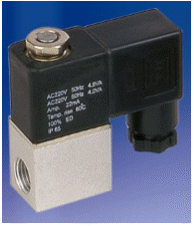
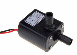
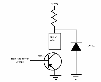
Since a GPIO pin from the Raspberry Pi cannot supply enough power to drive either the pump or the valve, a power transistor must be used to switch on power to the pump or valve. The same circuit can be used to supply power to the pump or valve. A TIP31 NPN power transistor with a 1N4001 power diode can be used to interface the GPIO pin to the the valve or pump. The resistor will be sized to limit the current and handle the power. One driver circuit will be required for each pump.
After considering the attributes of each candidate design, the pump alternative was chosen because it was less expensive. Furthermore, the valve design would require that the reservoir would be above the ground at least 1 meter and this can cause physical stability problems.
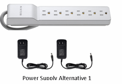
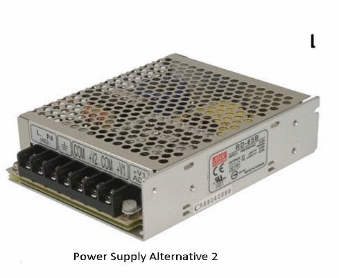
Two possible configurations of power supply design were considered. The worst case scenario for the 12 VDC supply is when all 4 pumps are running simultaneously. This would require a 12 VDC power supply that could source 1.6 amps. The worst case for the 5 VDC power is is that it source 700mA to run the Raspberry Pi 3 B. The first power supply design uses a 12 VDC 2 Amp wall outlet adapter at $8.99, a 5 VDC 1 amp wall adapter at $2.89 and an 8 outlet strip with switch at $7.99 for a total of $19.97. The second design would use an AC-DC dual output 5 VDC 8 amp 12 VDC 4 amp switch mode, open frame power supply at $19.95 and a 120 VAC SPST switch at $3.49 for a total of $23.44. The second design alternative would be a more self contained design. However, it would take some fabrication time and is slightly more expensive than the first alternative. The first design alternative is more clunky but easier to implement. Since there is a severe time constraint, the first design alternative was chosen.
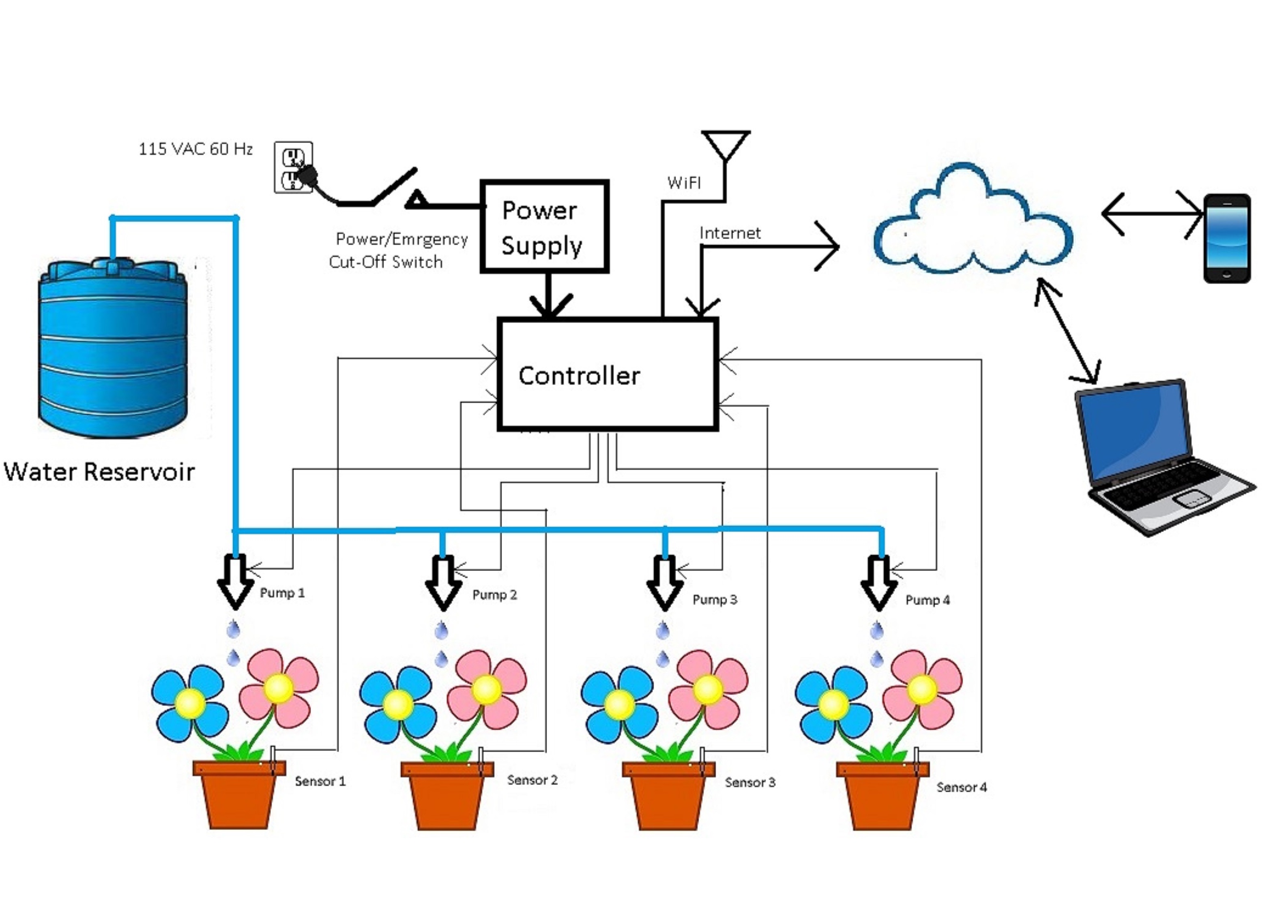
The controller will be built inside a 12” X 5” X 3” plastic project box. The Raspberry PI and proto-board will be mounted inside the box. The electronic drivers will be soldered onto the proto-board and connection to the Raspberry Pi will be made with ribbon cable. Connections to the pumps and sensors will be made to the controller via individual cables connecting to a panel mount connector on the control box which then connects to the proto-board. The moisture sensors plug directly into the soil they are measuring. The submersible pumps will mount directly to the bottom of the reservoir. The pumps will supply water to the plants via flexible vinyl hoses. The reservoir will be implemented by using a five gallon paint bucket. DC panel mount plugs will be mounted on the plastic box so that the wall adapters can plug directly into the controller.
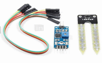
After an extensive internet search, only one type of moisture sensor met the requirements. The sensor selected was an Arduino (and Raspberry Pi) compatible moisture sensor. The sensor features a comparator with a potentiometer that can adjust the detection threshold of the sensor. The output of the sensor can connect directly to a Raspberry Pi GPIO pin without any additional interface electronics.
The software will be designed using the Python 3 (IDLE) that will be downloaded onto the Raspberry Pi in the controller. It is expected that the majority (approx 80%) of the design implementation effort will be the design and testing of the software. The complete design implementation is expected to take 1 month. The total estimated cost of implementation is calculated in the following table.
|
|
each |
subtotal |
|
Raspberry Pi 3 B |
$35.00 |
$35.00 |
|
pumps |
$11.69 |
$46.76 |
|
sensors |
$5.99 |
$23.96 |
|
Project box |
$30.00 |
$30.00 |
|
reservoir |
$4.68 |
$4.68 |
|
Vinyl hose |
$.35/ft |
$7.00 (20 feet) |
|
Power supply |
$23.44 |
$23.44 |
|
Miscellaneous (transistors, diodes proto-board, connectors, wire) |
$10.00 |
$10.00 |
|
total |
|
$180.84 |
The following diagram shows the final system block diagram, with the four moisture sensors in each of the four pots, the four pumps connected by vinyl hoses to the reservoir, the electrical connections to the sensors, pumps and controllers and the communication to the controller via tweets through the cloud.
